1Dof spring mass damper system by Michael Alletto
- contributor: Michael Alletto
- affiliation: WRD MS
- contact: click here for email address
- OpenFOAM versions: v2006
- Published under: CC BY-NC-ND license (creative commons licenses)
Go back to Collection by authors.
Go back to Meshing.
Contents
1Dof spring mass damper system
You can download the case file [1] here.
Introduction
Fluid structure interaction is associated with a multitude of physical phenomena: the stability and response of aircraft wings, the flow through arteries, the vibration of heat exchanger, the vibration of compressor and turbine blades and many more [1]. In order to capture this phenomena accurately, it is important to sorrowfully validate both fluid and structure solvers first separately and after that both together. In this spirit, in this small tutorial we show a small validation case of the six degree of freedom solver of OpenFOAM. This solver is responsible to advance the location of a rigid body subject to fluid forces and restrains like springs and damper in time.
Set up
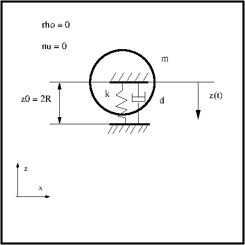
The next figure shows the setup of the simulation: We have a closed square with a fluid initially at rest. Actually the fluid part does not play a role in this tutorial since we are interested only in the movement of the one degree of freedom spring-mass-damper system. In order to exclude any influence of the fluid force on the movement of the circular cylinder we set the density ρ and the viscosity ν to zero (actually to a very small value to avoid possible divisions by zero). In this way the pressure force which acts normal to the solid body surface and the shear stress which acts parallel to it do not influence the motion of the cylinder.
The mass m is set to m = 0.03575 kg, the spring constant k of the linear spring is set to k = 69.48 N/m. Two different damping cases are considered. The first one is an undamped system. In the second case the damping constant d is set to d = 0.0039 Ns/m which corresponds to a weakly damped system. For undamped and weakly damped systems the oscillation induced by the fluid on the structure can have potentially disastrous effects. The spring has an initial extension of z0 = 0.0016 m which corresponds to the diameter of the cylinder.
For this configuration we have an analytical solution which we can use to verify our solver:
z/z0 = exp(-0.5(d/m)t)cos((k/m)0.5t)
Mesh generation
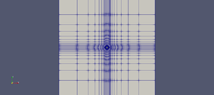
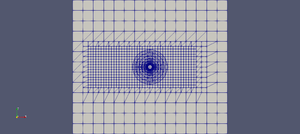
In this tutorial we will compare the results of two solvers: overPimpleDyMFoam and pimpleFoam. The first solver uses the overset method to account for the displacement of the solid body and the second one the morphing mesh method. The reason we chose to compare this two solvers even if we are only interested in the solid body motion solver a twofold: The first one is for consistency. Since in the previous tutorial (see [2]) we compared this two solvers and in a follow up tutorial we will do the same, it is consistent to do the same here. This tutorials belong to a series which aim to verify the capability of OpenFOAM to simulate vortex induced vibrations on circular cylinders. The second reason is that the solver overPimpleDyMFoam does not allow to update the spring and damper force during the outer iteration of the pimple loop. We will see that this leads to an unstable numerical method for the undamped spring-mass system if the Newmark method is used. The meshes generation is taken from the tutorial [3] and are shown in the below figures:
Since we are not interested in the fluid solution the amount of cells are kept very low: 1267 for the overset mesh and 868 for the morphing mesh.
Simulation set up
The following two listings shows the settings of the dynamicMeshDict. In this dictionary the parameters for the sixDoFRigidBodyMotion solvers are set. The only difference between the morphing mesh and the overset mesh is in the entry dynamicFvMesh. We set two constrains for the rigid body motion: One is that the cylinder can displace only along the z-axis and we also blocked the rotation around the y-axes. In order that the fluid force has no influence on the body motion we set the density rhoInf to 1.0e-15. The viscosity in the dictionary constant/transportProperties is set to the same value. The spring has an initial extension of 0.0016 m which corresponds to the diameter of the cylinder.
Entry for the overset mesh:
motionSolverLibs (sixDoFRigidBodyMotion);
motionSolver sixDoFRigidBodyMotion;
displacementLaplacianCoeffs
{
diffusivity uniform 1;
}
dynamicFvMesh dynamicOversetFvMesh;
dynamicOversetFvMeshCoeffs { // layerRelax 0.3; }
sixDoFRigidBodyMotionCoeffs {
   accelerationRelaxation 1.0;
   accelerationDamping 1.0;
   patches         (walls);
   innerDistance   1.0;
   outerDistance   1.1;
   mass            0.03575;
  centreOfMass    (-0.016 0.0 0.0016);
  momentOfInertia (4.3472E-07 1.144E-08 4.3472E-07);
  g               (0 -9.81 0);
  rho             rhoInf;
  rhoInf          1.0e-15;
  report          on;
  solver
  {
      type symplectic;
  }
  constraints
  {
   zLine
   {
       sixDoFRigidBodyMotionConstraint line;
       centreOfRotation    (-0.016 0.0 0.0);
       direction           (0 0 1);
   }
   yAxis
   {
       sixDoFRigidBodyMotionConstraint orientation;
       centreOfRotation                (0 1 0);
   }
}
restraints
{
   verticalSpring
   {
       sixDoFRigidBodyMotionRestraint linearSpring;
       anchor          (-0.016 0.0 0.0);
       refAttachmentPt (-0.016 0.0 0.0016);
       stiffness       69.48;
       damping         0.00;
       restLength      0;
   }
}
}
Entry for the morphing mesh:
motionSolverLibs (sixDoFRigidBodyMotion);
motionSolver sixDoFRigidBodyMotion;
displacementLaplacianCoeffs
{
diffusivity uniform 1;
}
dynamicFvMesh dynamicMotionSolverFvMesh;
dynamicOversetFvMeshCoeffs { // layerRelax 0.3; }
sixDoFRigidBodyMotionCoeffs {
   accelerationRelaxation 1.0;
   accelerationDamping 1.0;
   patches         (cylinder);
   innerDistance   1.0;
   outerDistance   1.1;
   mass            0.03575;
  centreOfMass    (0.0 0.0 0.0016);
  momentOfInertia (4.3472E-07 1.144E-08 4.3472E-07);
  g               (0 -9.81 0);
  rho             rhoInf;
  rhoInf          1.0e-15;
  report          on;
  solver
  {
      type symplectic;
  }
  constraints
  {
   zLine
   {
       sixDoFRigidBodyMotionConstraint line;
       centreOfRotation    (0.0 0.0 0.0016);
       direction           (0 0 1);
   }
   yAxis
   {
       sixDoFRigidBodyMotionConstraint orientation;
       centreOfRotation                (0 1 0);
   }
}
restraints
{
   verticalSpring
   {
       sixDoFRigidBodyMotionRestraint linearSpring;
       anchor          (0.0 0.0 0.00);
       refAttachmentPt (0.0 0.0 0.0016);
       stiffness       69.48;
       damping         0.0039;
       restLength      0;
   }
}
}
In the following we will explain the most important parameters in the dynamicMeshDict.
The entry accelerationRelaxation description how much the acceleration of the new time step is underrelaxed. It means that if the entry is 1 the acceleration calculated for the current time step is taken as it is for the calculation of the solid body displacement and velocity. If it is set to 0.5, the acceleration calculated for the current time step is multiplied by 0.5 and added to the acceleration of the previous time step which is also multiplied by 0.5. The function where this calculation is performed can be found in $FOAM_SRC/sixDoFRigidBodyMotion/sixDoFRigidBodyMotion/sixDoFRigidBodyMotion.C:
void Foam::sixDoFRigidBodyMotion::updateAcceleration
(
   const vector& fGlobal,
   const vector& tauGlobal
)
{
static bool first = true;
   // Save the previous iteration accelerations for relaxation
   vector aPrevIter = a();
   vector tauPrevIter = tau();
   // Calculate new accelerations
   a() = fGlobal/mass_;
   tau() = (Q().T() & tauGlobal);
   applyRestraints();
   // Relax accelerations on all but first iteration
   if (!first)
   {
       a() = aRelax_*a() + (1 - aRelax_)*aPrevIter;
       tau() = aRelax_*tau() + (1 - aRelax_)*tauPrevIter;
   }
   else
   {
       first = false;
   }
}
The entry accelerationDamping is a factor which is multiplied with the acceleration used to calculate the new velocity and the new position in the motion solvers. As example code we will show the function solve in the symplectic solver (the factor aDamp() is also found in the Newmark solver). The file can be found in $FOAM_SRC/sixDoFRigidBodyMotion/sixDoFSolvers/symplectic/symplectic.C
void Foam::sixDoFSolvers::symplectic::solve
(
   bool firstIter,
   const vector& fGlobal,
   const vector& tauGlobal,
   scalar deltaT,
   scalar deltaT0
)
{
   // First simplectic step:
   //     Half-step for linear and angular velocities
   //     Update position and orientation
   v() = tConstraints() & (v0() + aDamp()*0.5*deltaT0*a0());
   pi() = rConstraints() & (pi0() + aDamp()*0.5*deltaT0*tau0());
centreOfRotation() = centreOfRotation0() + deltaT*v();
   Tuple2<tensor, vector> Qpi = rotate(Q0(), pi(), deltaT);
   Q() = Qpi.first();
   pi() = rConstraints() & Qpi.second();
   // Update the linear acceleration and torque
   updateAcceleration(fGlobal, tauGlobal);
   // Second simplectic step:
   //     Complete update of linear and angular velocities
   v() += tConstraints() & aDamp()*0.5*deltaT*a();
   pi() += rConstraints() & aDamp()*0.5*deltaT*tau();
}
The entry patches provides a list of boundary patches for which the fluid forces are integrated.
The entry mass provides the mass of the solid body.
The entry centreOfMass describes the position of the center of mass of the body.
The entry momentOfInertia describes the principal components of the inertia tensor (see e.g. [4]). That means that at the beginning of the simulation the Cartesian coordinate system must align with the principal axis of the inertia tensor. (see also [5]). For simple bodies the page [6] provides a list of moments of inertia. In our case we have a solid cylinder with the mass m, the radius r and the height h. The inertia moment around the axis of the cylinder (in our case the y-axis) is calculated as follows:
Iy = 0.5 m r2
Around the other two axis (the x- and z-axis) it is calculated as follows:
Ix = Iz = 1/12 m ( 3r2 + h2 ).
By inserting the values of m = 0.03575 kg, r = 0.0008 m and h = 0.012 m we get the values inserted in the dictionary.
Note however that in this tutorial the value of the moment of inertia does not play a role since the rotational degree of freedom is blocked.
As stated already above, we applied two constrains to the body: The first one is that the body can move only along the z-axis going through the point (0.0 0.0 0.0016) and the second one is that the rotation around the y-axis is suppressed. The rotation around the other two axis are suppressed implicitly since it is a 2D problem.
The linear spring-damper restrain is applied in order to obtain an oscillatory motion of the body. The anchor is set to (0.0 0.0 0.00) (it is the point to which the spring is anchored) and the point to which the spring-damper is attached to the body is set to (0.0 0.0 0.0016). In this way the spring has an initial extension of one diameter.
Results
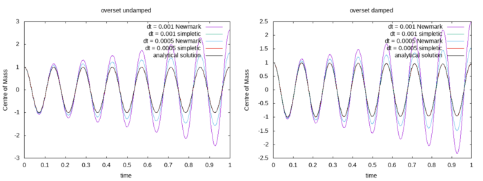
The next figure shows the results obtained by the overset mesh. Two different time step sizes of dt = 0.0005 s and dt = 0.001 s are compared with each other. Furthermore two different method to integrate the ordinary differential equation are investigate: the implicit Newmark method and the explicit symplectic method. It has to be mentioned that the Newmark method for the overset method is also explicit since the spring and damper force are not updated during the outer iterations of the simple loop. It is obvious that the Newmark method is unstable for both undamped and weakly damped system. The error decreases with decreasing time step. The symplectic method reproduces the analytical result exactly.
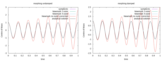
The next results shown are obtained for the morphing mesh. Four different simulation are performed for the undamped (left) and damped case (right). The time step size was dt = 0.001 s. For one simulation the symplectic method was used to compute the evolution of the velocity and position of the solid. For the other three the Newmark method was used. For one simulation the acceleration of the solid body was not update during the outer iterations (labeled as Newmark no outer correction). For the remaining simulations the acceleration of the solid body was updated during the two (labeled as Newmark 2 outer) and four (Newmark 4 outer) outer iterations. It is evident that for the undamped case and the simulation where the acceleration is not updated during the outer iterations the solution obtained is not stable. For all other cases the numerical solution is identical to the analytical.
Lessons learned
- It is very useful to verify numerical methods with analytical solutions. From my experience as model developer and programmer one can get rid of the majority of bugs and errors in the settings if one compares the results of the simulation with an analytical solution where one exactly knows the outcome.
- If the overset mesh is used, it is recommended to use the symplectic solver since for the Newmark method the acceleration of the solid body is not updated during the outer iterations and the solver is in fact an explicit one.
- If the morphing mesh is used, it is recommended to update the acceleration of the solid body during the outer iterations if the Newmark method is used.
References
[1] Earl H Dowell and Kenneth C Hall. Modeling of fluid-structure interaction. Annual review of fluid mechanics, 33(1):445–490, 2001.
