NACA0012 angle of attack by Michael Alletto
- contributor: Michael Alletto
- affiliation: WRD MS
- contact: click here for email address
- OpenFOAM versions: v1912
- Published under: CC BY-NC-ND license (creative commons licenses)
Go back to NACA0012 tutorial page.
Contents
Angle of attack
Files can be downloaded here.
Comparison with experiments at different angles of attack and Mach numbers
Having found a satisfactory setup at a fixed parameter set (in our case the Mach number and the angle of attack) we have to test if this setup (the combination of grid resolution, numerical schemes and turbulence model) works well also for other Mach numbers and angles of attack.
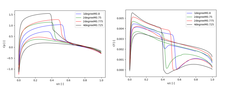
The figure below shows the evolution of the pressure coefficient and friction coefficient for the 4 different cases simulated here: Ma = 0.75 α = 2° (labeled as 2degreeM0.75), Ma = 0.8 α = 1° (labeled as 1degreeM0.8), Ma = 0.775 α = 2° (labeled as 2degreeM0.775) and Ma = 0.725 α = 4° (labeled as 4degreeM0.725). The purpose of this figure is to verify if the current setting reproduces qualitatively the influence of the Mach number and angle of attack regarding the resulting flow picture.
Following the description of [6] with increasing Mach number and angle of attack the extension of the supersonic flow region increases. The strength of the shock increases too, leading potentially to a shock induced separation. Comparing the two simulations with an angle of attack of 2°, we see that the shock position is further downstream for the higher Mach number. The strength of the shock is highest for the highest angle of attack leading to a small shock induced recirculation bubble. In fact this highest angle of attack is the only one where the friction coefficient is negative on the upper side of the airfoil indicating the presence of a reversed flow. These observations indicate that the qualitative behavior of the current setup regarding the Mach number and angle of attack is in line with the one describe in the review article of [6].
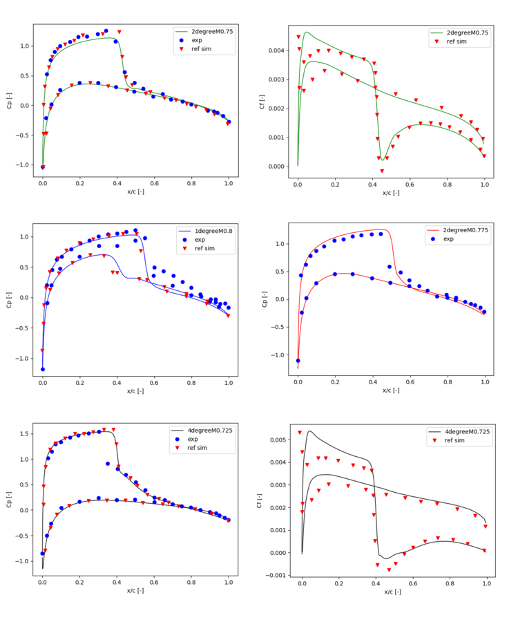
The next figure shows the comparison of the current simulations with the reference experiment of [5] and the simulations of [4]. Following observation can be made:
1) For all cases where the reference simulation is present (which used the same turbulence model but fully resolved the wall) the agreement is remarkably good.
2) For the case with an angle of attack of 2° also the agreement with the experiments is very good.
3) For the 4° case the shock position is predicted at a location farther downstream as the reference experiment.
4) For the 1° case the position of the shock at the lower site of the airfoil is predicted too far upstream. The same holds for the simulations of [4] while the experiments report that for both sides of the airfoil the shock is approximately at the same position in downstream direction.
Conclusions which can be drawn from the results of the stationary airfoil
The main parameter which influence the simulation of the turbulent flow around a transonic airfoil are evaluate in the former sections (the size of the computational domain was chosen in accordance to other simulation and therefore it is supposed to be sufficient large to neglect the influence of the boundary conditions on the region close to the airfoil).
From the variation of the resolution we found a grid for which the main quantity of interest in this tutorial, i.e. the distribution of the pressure on the surface of the airfoil, does not change substantially compared to finer grids. This allows as to find a fairly good compromise between computational demand and accuracy. The scope of this study was to find a suitable grid for the simulation of the attached flow around a periodically pitching airfoil using wall functions. Since the case used to perform the grid independence study was of this type of flows, we are fairly optimistic that the grid size found is also suitable for the final goal.
After that we varied the discretization used for the convective term in the pressure, momentum, energy and turbulence equation. We found that it is important to use a central scheme to discretize the convective term in the pressure equation to accurately resolve the shock. For the convective term in the momentum equation it is important to use a second order scheme. The linear and the second order upwind scheme give similar results. The other descetization schemes have a minor importance.
The variation of the turbulence model lead us to the conclusion that the Spalart-Allmaras model gives reasonable results for attached transonic flows. The same conclusion can be found also in a variety of other studies (see e.g. [1-4]).
Finally we compared the found setup with experiments and simulations for other angles of attack and Mach numbers. For all cases the results agreed reasonably.
All this evaluations gives as confidence that we found a good setup for the simulation of the periodically pitching airfoil.
References
[1] G Barakos and Dimitris Drikakis. Numerical simulation of transonic buffet flows using various turbulence closures. International Journal of Heat and Fluid Flow, 21(5):620-626, 2000.
[2] Enda Dimitri Vieira Bigarella and Jo~ao Luiz F Azevedo. Advanced eddyviscosity and reynolds-stress turbulence model simluations of aerospace applications. AIAA journal, 45(10):2369-2390, 2007.
[3] Pietro Catalano and Marcello Amato. An evaluation of rans turbulence modelling for aerodynamic applications. Aerospace science and Technology, 7(7):493-509, 2003.
[4] Michael Iovnovich and Daniella E Raveh. Reynolds-averaged navierstokes study of the shock-buffet instability mechanism. AIAA journal, 50(4):880-890, 2012.
[5] John B McDevitt and Arthur F Okuno. Static and dynamic pressure measurements on a naca 0012 airfoil in the ames high reynolds number facility. 1985.
[6] H Tijdeman and R Seebass. Transonic flow past oscillating airfoils. Annual Review of Fluid Mechanics, 12(1):181-222, 1980.

