Vortex induced vibration of a 2D cylinder by Michael Alletto
- contributor: Michael Alletto
- affiliation: WRD MS
- contact: click here for email address
- OpenFOAM versions: v2112
- Published under: CC BY-NC-ND license (creative commons licenses)
Go back to Collection by authors.
Go back to Meshing.
Contents
Vortex induced vibration of a 2D cylinder
You can download the case file https://gitlab.com/mAlletto/openfoamtutorials/-/tree/master/transverseRe100m*10] here.
Introduction
In this tutorial we will examine the capability of OpenFOAM to simulate the vortex induced vibration on a circular cylinder in a 2D laminar configuration. The cylinder is free to vibrate in stream wise and in transverse direction. This kind of flow configuration is often used to validate codes which aim to describe the interaction of a fluid with a solid structure (see e.g. [3],[6]).
Besides that, this configuration is used to answer fundamental questions of the basic physical mechanisms playing a role in the interaction between the flow and the solid body (see e.g. the review of [8]). Recent studies concentrate on the phenomena which lead to large amplitude oscillation of the cylinder and the synchronization of the vortex shedding frequency with the natural frequency of the spring-mass-damper system (see [1],[5]).
This tutorial is the final tutorial of a series of three which aims to illustrate how to validate a complex simulation task: It is convenient to break the problem first down into smaller easier sub tasks. In our example series before simulating the final problem of the vortex induced oscillations of a circular cylinder, we first simulated a fixed cylinder (see [1]), than a moving cylinder with a prescribed motion (see [2]), after that we checked the performance of the six degree of freedom body solver against an analytical solution (see [3]) and only as last point we tackled the simulation of the cylinder mounted elastically in a moving fluid. With this kind of procedure it is much easier to isolate eventual errors of the settings or maybe also bugs in the underlying code.
Set up
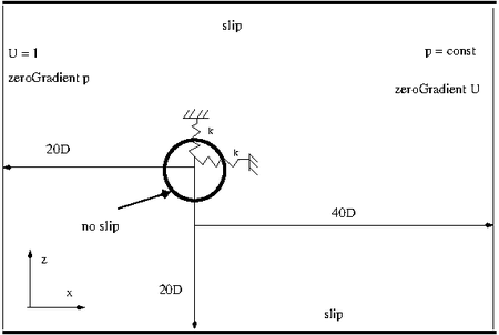
The next figure shows the setup of the simulation: At the inflow a uniform velocity of Uoo = 0.0656 m/s in x-direction is applied. The pressure is set to zero gradient at this boundary. At the top and bottom walls a slip boundary condition is applied. At the outlet the pressure is to be set equal to zero and for the velocity a zero gradient boundary condition is applied. The kinematic viscosity v = 1.05 x 10⁻⁶ m2/s is set in order that the Reynolds number Re = Uoo D / v based on the cylinder diameter D = 0.0016 m is equal to Re = 100. For this Reynolds number the flow over a stationary cylinder is two dimensional. For this reason the flow is assumed to be two dimensional. This is imposed by using only one cell in span wise direction and setting both boundary conditions in this direction to the type empty. At the cylinder wall a no slip boundary condition is applied for the velocity and zero gradient for the pressure. The cylinder is free to oscillate in x- and y-direction. In this direction a linear spring restrain type is applied. The linear damping is set to zero in order to be comparable with the reference simulation of [7]. The domain extends 20 D in upstream direction, 40 D in downstream direction and 20 D in both lateral direction. For this size of the computational domain [4] found that the results are almost independent of the location of the boundaries.
Four different non dimensional velocities are computed: U* = Uoo/(fn D) = 4, 4.8, 5 and 8.5. Uoo is the incoming flow velocity and fn = ω/(2 π) = (k / m)0.5/(2 π) is the natural frequency of the spring-mass system. The lowest and highest non-dimensional velocity correspond to cases in [7] where the shedding frequency is not synchronized with the spring-mass system and therefore low amplitude oscillation of the mass occur. A U* = 4.8 correspond to the onset of synchronization with large amplitude oscillation (z/D approximately 0.6) in the reference experiment. A U* = 5.5 correspond to a region in the middle of the synchronization regime. Also for this case the reference experiment reportes large amplitude oscillations. Having defined the diameter D of the cylinder, the incoming flow velocity Uoo and the mass m = 0.03575 kg, after that, one can determine the four different linear spring constants k = 148.2, 102.97, 78.42 and 32.83 N/m to obtain a non-dimensional velocity of U* = 4, 4.8, 5.5 and 8.5, respectively. The last non-dimensional parameter to match is the non-dimensional mass m* = m / mf = 4 m / (π ρ D2 H) = 10. H = 0.12 m is the height of the cylinder. In order to match this non-dimensional parameter the density is set to 14817 kg / m3.
Mesh generation
The next figure shows the two mesh types compared: On the left the overset mesh and on the right the morphing mesh. The overset mesh consists in a cylindrical mesh immersed in different rectangular regions. The morphing mesh also consists in a cylindrical region in the center which is connected with hexagonal cells to the outer boundaries. Note that the cylindrical regions in the overset mesh and the morphing mesh are identical for better comparability of the results. The two mesh types (overset and morphing mesh) are essentially taken from this tutorial: [4]. For this reason how they are generated is not described in more detail.
Simulation set up
The next listing shows the dynamicMeshDict for the overset mesh. For the morphing mesh it is almost the same. The only thing which changes is the entry for dynamicFvMesh. The basic difference to the tutorial described in [5] is that the motion is constrained in the y-plane instead of along the z-axis.
motionSolverLibs (sixDoFRigidBodyMotion);
motionSolver sixDoFRigidBodyMotion;
displacementLaplacianCoeffs
{
diffusivity uniform 1;
}
dynamicFvMesh dynamicOversetFvMesh;
dynamicOversetFvMeshCoeffs { // layerRelax 0.3; }
sixDoFRigidBodyMotionCoeffs {
   accelerationRelaxation 1.0;
   accelerationDamping 1.0;
   patches         (walls);
   innerDistance   1.0;
   outerDistance   1.1;
   mass            0.03575;
  centreOfMass    (-0.016 0.0 0.0);
  momentOfInertia (4.3472E-07 1.144E-08 4.3472E-07);
  g               (0 -9.81 0);
  rho             rhoInf;
  rhoInf          14817.;
  report          on;
  solver
  {
      type symplectic;
  }
  constraints
  {
   yPlan
   {
      sixDoFRigidBodyMotionConstraint   plane;
      normal ( 0 1 0);
   }
   yAxis
   {
       sixDoFRigidBodyMotionConstraint orientation;
       centreOfRotation                (0 1 0);
   }
}
restraints
{
   verticalSpring
   {
       sixDoFRigidBodyMotionRestraint linearSpring;
       anchor          (-0.016 0.0 0.0);
       refAttachmentPt (-0.016 0.0 0.0);
       stiffness       32.83;
       damping         0.00;
       restLength      0;
   }
}
}
Note the we chose the symplectic solver for the solution of the displacement of the solid body. The reason is that we found out in the tutorial [6] that the Newmark (and also the Crank Nicolson which is equal to the Newmark method for the default parameters) is unstable if the spring forces are treated explicitly. This underlines the necessity to validate each sub component of a complex simulation method separately before tackling the combined problem to reduce erroneous settings to a minimum.
Results
As advisable for every new simulation technique, we start with a small mesh convergence study. A mesh convergence study allows to guess the numerical errors (at least for laminar flows where no modeling errors are introduced) and to find a trade off between accuracy and time to solution.
For this purpose we analyzed two overset meshes: one with 16 700 and one with 7 700 cells. Two morphing meshes one with 12 700 and one with 7 400 cells are compared as well.
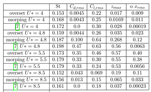
The results obtained for the St number St = f D / U, the r.m.s drag coefficient Cd,rms, the r.m.s lift coefficient Cl,rms, the r.m.s of the x-displacement xrms and the maximum z-displacement zmax are shown in the next figure. The shedding frequency f is calculated using the time signal of the lift force. The results are compared with the simulations of [7]. From this integral coefficients it is evident that no big differences are visible between the coarse and fine overset mesh and the coarse and fine morphing mesh. For this reason all further computation are made with the coarse version of both meshes in order to save computational resources. The morphing mesh simulations agree well with the reference simulation except for the root mean square displacement in x-direction xrms. The reason for this discrepancies are not very clear. Note that the python scripts used to calculate this quantities are included in the tutorial material.
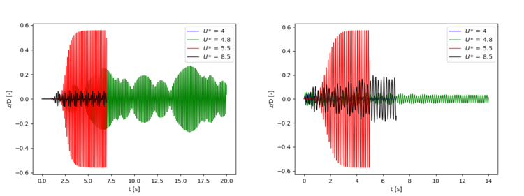
The next table compares the St number, the r.m.s drag coefficient Cd,rms, the r.m.s lift coefficient Cl,rms, the r.m.s of the x-displacement xrms and the maximum z-displacement zmax for different U* with the simulations of [7]. It is evident that the best agreement with the reference simulation is obtained for the morphing mesh. For U* = 4.8 were [7] obtained already a locked in state, the overset mesh simulation reports only small oscillation and the morphing mesh simulation seems to be in a transitional regime right before the onset of lock in (see the figures displaying the evolution of the z-displacement). For the highest non-dimensional velocity U* = 8.5 the overset mesh predicts higher oscillations compared with [7] and the morphing mesh. It has be be said that this U* lays very close to the end of the lock in region reported in [7]. It seems that the boarders of the lock in region obtainable with the overset mesh with the settings used in this tutorial are shifted towards higher U* compared with the morphing mesh and the reference simulation.
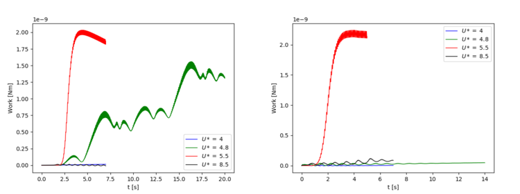
The next figure compares the work done from the start of the simulation (t = 0) until the time t by the fluid on the cylinder for the two mesh types and the four non-dimensional velocities analyzed. It is calculate (see also [7]):
Fz is the force in z-direction excreted by the fluid on the cylinder and vz is the z-velocity. According to [1],[2] the main mechanisms which leads to large amplitude oscillation is a positive energy transfer (or work done) over a oscillation cycle from the fluid to the oscillator. In order to check if this mechanisms can be found also in the present tutorial, we have plotted the following figure. It is evident that for the cases with large oscillations in z-direction the work done experiences a sharp increase and after that it remains constant. The large work done by the fluid is necessary to increase the amplitude of the displacement. After that a mean steady state is reached the work done of the fluid over an oscillation cycle has to be zero for the present simulations without structural damping [1]. For this reason the total work done by the fluid on the oscillator convergence to a constant value.
The next figure show the temporal evolution of the z-displacement of the cylinder for the overset mesh (left) and the morphing mesh (right). It is evident that the maximum displacement is observed for an U* = 5.5 for both meshes. For U* = 4 both mesh types show small oscillations. A remarkable difference between the two mesh types is observed for U* = 4.8: While for the overset mesh the amplitude of the oscillations is still small as in the pre-lock in regime, for the morphing mesh we can observed an intermittent behavior as observed by [4] in the small transition region before lock in occurs. For a U* = 8.5 the amplitude of the overset mesh is higher compared to the morphing mesh.
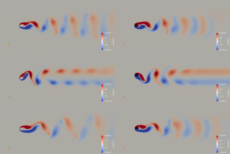
The next figure shows a snapshot of z-vorticity for the overset (left) and morphing (right) mesh for an U* = 4 (top), U* = 5.5 (middle) and U* = 8.5 (bottom). For the first two non-dimensional velocities the shedding modes are different. For the lower non-dimensional velocity (U* = 4) the shedding mode is similar to a stationary cylinder: Two single vortecies are shed per cycle from the cylinder. This shedding mode is called 2P mode which is also observed by [4],[7] in the low amplitude case. For the high amplitude oscillations case this two vortecies merge giving rise to the C(2P) mode also observed by [4],[7]. The flow pictures obtained with the overset mesh and the morphing mesh are very similar for this two U*. For an U* = 8.5 were the fluid flow is outside the lock in regime the flow picture is again similar to a stationary cylinder resulting in a 2P mode. The same is observed also in [4],[7].
Lessons learned
- Both overset mesh and morphing mesh can predict the large amplitude oscillations of the cylinder in the lock in regime. Outside this regime (for lower and higher values of non-dimensional velocity U*) the reported amplitudes of the structural oscillations are low. Inside the lock in regime the two single vortecies shed per cycle merge resulting in the so called C(2P) mode. Outside the lock in regime the two single vortecies are maintained also farther downstream. The same observations are made also by [4],[7].
- It seems that the boarders of the lock in region obtainable with the overset mesh with the settings used in this tutorial are shifted towards higher U* compared with the morphing mesh and the reference simulation.
- For the current settings the morphing mesh is up to three times faster compared with the overset mesh for similar number of cells. For this reason it is better to use the former if the movements of the structure are not too large to deteriorate the mesh quality.
- The work done by the fluid on the cylinder is highest for the cases with the highest amplitude oscillations.
References
[1] Sanjay Mittal et al. Lock-in in vortex-induced vibration. Journal of Fluid Mechanics, 794:565–594, 2016.
[2] TL Morse and CHK Williamson. Prediction of vortex-induced vibration response by employing controlled motion. Journal of Fluid Mechanics, 634:5, 2009.
[3] Marie Pomarede, Elisabeth Longatte, and Jean-Franc ̧ois Sigrist. Bench- mark of numerical codes for coupled csd/cfd computations on an elemen- tary vortex induced vibration problem. In ASME Pressure Vessels and Piping Conference, volume 43673, pages 537–546, 2009.
[4] TK Prasanth and Sanjay Mittal. Vortex-induced vibrations of a circular cylinder at low reynolds numbers. Journal of Fluid Mechanics, 594:463, 2008.
[5] Diogo Sabino, David Fabre, JS Leontini, and D Lo Jacono. Vortex- induced vibration prediction via an impedance criterion. Journal of Fluid Mechanics, 890, 2020.
[6] Linwei Shen, Eng-Soon Chan, and Pengzhi Lin. Calculation of hydro- dynamic forces acting on a submerged moving object using immersed boundary method. Computers & Fluids, 38(3):691–702, 2009.
[7] SP Singh and S Mittal. Vortex-induced oscillations at low reynolds num- bers: hysteresis and vortex-shedding modes. Journal of Fluids and Struc- tures, 20(8):1085–1104, 2005.
[8] CHK Williamson and R Govardhan. Vortex-induced vibrations. Annu. Rev. Fluid Mech., 36:413–455, 2004.
