Settling Sphere Contact Angle by Michael Alletto
- contributor: Michael Alletto
- affiliation: WRD MS
- contact: click here for email address
- OpenFOAM versions: v1906
- Published under: CC BY-NC-ND license (creative commons licenses)
Go back to Collection by authors.
Go back to Meshing.
Contents
Sphere settling under the influence of gravity with varying contact angle
You can download the case file sphereSplashSend.tar.gz here.
Introduction
This tutorial has two main objectives:
In this tutorial the capabilities of the overset methodology of OpenFOAM are further explored. In the previous tutorial a sphere settling under the influence of gravity was simulated (see).
It was shown, that the temporal evolution of the displacement and the velocity of a sphere settling in a viscous fluid is well captured. This means that the viscous and pressure forces integrated over the sphere surface are well captured. Furthermore it also means that the interpolation errors introduced by the overset methodology are not too big.
In order to systematically explore the capabilities of the overset methodology, the degree of complexity is only slightly increased compared to the previous tutorial: In this tutorial the impact of a solid sphere on a liquid surface is simulated. With reference to the previous tutorial the Reynolds number is increased from 1.5 to approximately 5000. Even though the Re-number is increased quite a lot, the boundary layer still remains laminar (see [1] for experiments around a sphere). This means that no turbulence model has to be used. For this reason, the main difference to the previous tutorial is the impact of the solid sphere at a gas-liquid interface. Regarding this event, quite recently an interesting phenomena was observed experimentally (see [3]) and also simulated (see [2]):
When a sphere with a hydrophobic coating impacts on a gas-liquid interface, a big air cavity is formed behind the sphere. In case of a hydrophilic coating, the liquid is able to enclose the sphere completely while impacting on the interface and no air cavity is formed behind the sphere. When the event is recorded by a microphone, a big splash is heard for the first case and only a blob for the second [3].
Simulation set up
In this section the set up of the simulation is shown step by step and the choice of the parameters employed is tried to be justified whenever it is possible.
Mesh generation
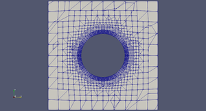
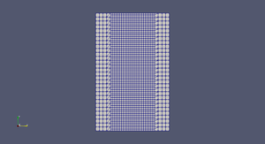
As in every CFD simulation the first step is to decide the domain extension and how to generate an adequate mesh which guarantees a desired solution quality. In this case the extension of the domain is obvious since the experimental setting is bounded by six walls. Figures to the right show the two meshes generated for the sphere (on the left) and for the background mesh (on the right). The figures show a slice through the mid plane of the mesh.
The mesh around the sphere was generated with snappyHexMesh adding a few layers close to the wall. The fine resolution of the boundary layer is necessary to correctly predict the viscous and pressure forces which are later use to displace the sphere in the domain. The outer boundary should not be chosen to be too close to the sphere wall. The reason is to avoid that the errors generated by interpolating the solutions between the two meshes are affecting the boundary layer close to the sphere. However the outer boundary should not be chosen too far away in order to avoid the contact of the mesh around the sphere with the domain boundaries. Note that when generating the meshes which are displacing in the domain the outer boundaries have to be assigned to the type overset.
The background mesh was generated with blockMesh and refining the mesh additionally with refineMesh in the domain centre where the mesh around the sphere is supposed to translate. The refinement is performed to reduce the interpolation errors between the background mesh and the mesh around the sphere. The interpolation errors are usually proportional to the cell size difference of the interpolation partners.
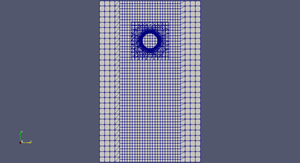
After generating the two distinct meshes the meshes can be merged by mergeMesh. The result is shown in the figure to the right.
Case set up
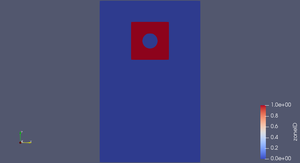
Before starting the simulation one has to ensure the a field named zoneID has to be present in the 0 folder. Each cell zone should have a different zone id starting with 0. In our case there a two zones: one is the background mesh and the other is the mesh surrounding the sphere (see also Figure to the right). As mentioned before, it is also necessary for the overset method to work that the outer boundaries of the meshes which are moving in the domain are declared as type overset.
Another field which is necessary for the mesh around the sphere to move is the one called pointDisplacement. For this field the sphere walls should be declared as type calculated. The reason is that the displacement of the sphere walls will be calculated by the motion solver.
The way to tell OpenFOAM that the mesh is changing is to have a file called dynamicMeshDict in the constant folder. There the settings for the motion solver have to made. The dynamicMeshDict is shown below. The displacement of the sphere (the patch named sphere) is calculated by the sixDoFRigidBodyMotion solver. It integrates the viscose and pressure forces over the patch to get the forces acting on the sphere. The displacement is than calculated by applying Newton's second law. Note that the mass has to be reduced by the Buoyancy since the overPimpleDyMFoam solver does not consider the hydrostatic pressure. In order to get a good agreement of the temporal evolution of the displacement and velocity of the sphere this is necessary.
motionSolverLibs ( "libsixDoFRigidBodyMotion.so" );
dynamicFvMesh dynamicOversetFvMesh;
dynamicOversetFvMeshCoeffs
{ // layerRelax 0.3; }
solver sixDoFRigidBodyMotion;
accelerationRelaxation 0.4;
sixDoFRigidBodyMotionCoeffs
{
patches (sphere);
innerDistance 100.;
outerDistance 101.;
accelerationRelaxation 0.4;
accelerationDamping 0.4;
// mass reduced by Buoyancy: (rhosolid - rhofluid ) * VolumeSphere
mass 2.65E-04;
centreOfMass ( 0 0 0 );
momentOfInertia ( 4.45E-08 4.45E-08 4.45E-08);
rho rhoInf;
rhoInf 970;
g (0 0 -9.81);
report on;
reportToFile on;
solver{ type Newmark;}
constraints{}
}
// ************************************************************************* //
After having made this settings, everything is ready to start with the simulation. Note that the maximum Courant number is changed during the simulation (it is done automatically by the timeActivatedFileUpdate function object). This is done in order to reduce the simulation time. In the beginning of the simulation a small maximum Courant number is required in order to keep the simulation stable. The reason is probably that the sudden movement of the sphere generates pressure oscillations which lead also to oscillations in the sphere displacement. This mutual coupling can destabilize the simulation.
Simulation results
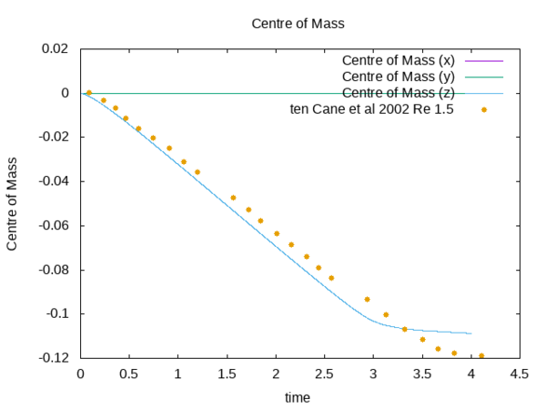
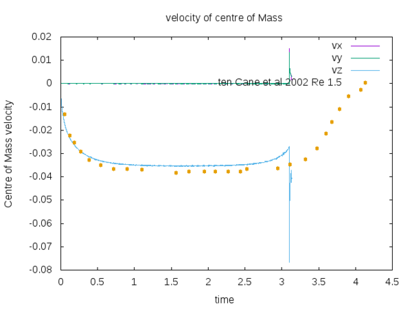
Finally the comparison with the experiments is shown in the figures below.
It is evident that good agreement could be achieved with the reference experiment until the mesh surrounding the sphere overpasses the bottom wall. Unfortunately than the simulation crashed. However the good agreement between the simulation and the experiments (at least for this case) helps to get confidence regarding the reliability of the overset method implemented in OpenFOAM.
[1] Elmar Achenbach. Experiments on the flow past spheres at very high reynolds numbers. Journal of Fluid Mechanics, 54(3):565-575, 1972.
[2] Minh Do-Quang and Gustav Amberg. The splash of a solid sphere impacting on a liquid surface: numerical simulation of the influence of wetting. Physics of Fluids, 21(2):022102, 2009.
[3] Cyril Duez, Christophe Ybert, Christophe Clanet, and Lyderic Bocquet. Making a splash with water repellency. Nature physics, 3(3):180, 2007.
[4] Jacco H Snoeijer and Bruno Andreotti. Moving contact lines: scales, regimes, and dynamical transitions. Annual review of fluid mechanics, 45:269-292, 2013.
