Lid driven cavity with a flexible bottom surface Michael Alletto
- contributor: Michael Alletto
- affiliation: WRD MS
- contact: click here for email address
- OpenFOAM versions: v2212
- Published under: CC BY-NC-ND license (creative commons licenses)
Go back to Collection by authors.
You can download the case https://gitlab.com/mAlletto/openfoamtutorials/-/tree/master/membranBCSend/testCases/nonLinMembraneStaightDisplacement/lidDrivenCavity] here.
Contents
Introduction
In this small tutorial we will see how to simulate a fluid structure interaction problem with the membrane boundary conditon shown in the tutorial https://wiki.openfoam.com/Coupling_a_simple_nonlinear_membrane_to_point_displacement_Michael_Alletto. The test case consists in the well kown lid driven flow. In order to allow for fluid structure interaction (FSI) the bottom wall is flexible. The same test case was already used in order to validate a number of FSI codes (see e.g. [1]-[3]).
Setup
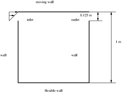
The setup of the simulation is shown in the following figure. It consists in a lid driven cavity case with some modifications. The difference to the classical case are the following: The bottom wall is flexible and is allowed to deform. The top wall is moving with a time varying velocity:
U = 1 - cos (2 pi t / 5).
The above boundary condition was implemented by using an expFixedValue boundary condition:
   movingWall
   {
       type            exprFixedValue;
       valueExpr
       #{
          vector (1,0,0) - vector(1,0,0)*cos(2*3.1416*time()/5)
       #};
   }
The main purpose of having a time varying velocity is to have a time varying pressure. This leads to a time varying deformation of the bottom membrane. The last modification compared to the classical lid driven cavity is that there is gap between the top and the side walls of a height of 0.125 m. The length of the four sides of the square is 1 m. The viscosity of the fluid is set to &nuf = 0.01 m2/s2. The velocity at the inlet was varied linearly between 0 at the lower part of the gap and a value of the time varying velocity at the top of the gap. This boundary condition was also achieved by using an exprFixedValue boundary condition: inlet
   {
       type            exprFixedValue;
       valueExpr
       #{
          (vector (1,0,0) - vector(1,0,0)*cos(2*3.1416*time()/5)) *
           (pos().y() - 0.875) / (1.0 - 0.875)
       #};
   }
The pressure was set to a zero gradient condition at the inlet. Regarding to the outlet the velocity was set to zero gradient and the pressure to a constant value of 0. The reason for the gap between the top wall and the side walls is to allow to set the pressure to zero at the outlet. This allows to fix the pressure value and allow a defined membrane movement. The membrane movement is dependent form the value of the pressure while the results in an incompressible fluid are only dependent from the gradient of the pressure. The Young modulus of the membrane located at the bottom wall was set to E = 250 N/m2, the density was set to &rho = 500 kg/m3$ and the Poisson ratio was set to &nu = 0.
In this small tutorial, we will perform three different simulations: Two simulation with the time varying velocity imposed at the top wall. The two simulations differ with respect to the number of cells used: One used a coarse mesh with a grid of 20x20 cells and a fine mesh of 40x40 cells. For the fine mesh we will perform also a simulation with a constant wall velocity of U = 1 m/s for comparison. The purpose is to check if the membrane deformation reaches a constant deformation which is comparable to the mean value of the deformation obtained for the time varying velocity.
Description of the FSI strategy adopted
The FSI strategy adopted in this tutorial belongs to the segregated approaches. Segregated means, that the flow and the structure are solved separately and coupled with explicit source terms. Furthermore a fixed point iteration is used to ensure that both fluid and structure reach a converged stage within a given time step. Briefly summarized the solution strategy works as follows:
advance simulation by one time step
While i < N
    Solve fluid
   transfer pressure to membrane equation
   solve the membrane equation
   move mesh according the displaced obtained by the membrane equations
EndWhile
go to next time step
In the above code, N represent the number of outer iteration specified in the fvSolution dictionary. Actually the while loop should be performed until the structure is converged, i.e., until the deformation computed in two successive iteration steps is less than a specified threshold. Since here we do not want to modify the solver pimpleFoam we need to choose a sufficiently large number of outer iterations in order to ensure that the structure converges.
Results
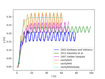
The next figure shows the results of the present computations with the references [1]-[3]. The vertical displacement of the membrane at the middle of the bottom wall (i.e. x = 0.5 m) is shown. It is evident that the vertical displacement of the present simulations is higher compared to the references simulation. The reason is probably that the membrane is displaced in direction of the initially undeformed surface. The frequency of the oscillations is equal to the one of the reference simulation. This is not surprising since the time varying deformation is caused by the time varying pressure at the surface of the membrane. The time varying pressure is causes by the time varying velocity imposed at the top surface. The vertical displacement of the case with a steady top velocity is approximately equal to the mean displacement of the time varying cases.
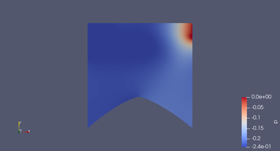
The next figure shows the configuration and the pressure distribution of the cavity for the steady state. We can observe the displacement of the membrane is caused by the negative pressure acting on its surface.
The next figure shows the pressure of the cavity of a time step of t = 58 s (left figure) and for a time step of t = 60 s (right figure). The chosen time steps correspond to approximately the minimum deflection and maximum deflection (t = 60 s) in vertical direction. For the time step where the deflection has a maximum the pressure is lower compared to the time step where the deflection has a minimum.
Lessons learned
- Decent results can be obtained by a simple membrane model with respect to the references in the literature
- OpenFOAM is capable to solve fluid structure interaction problems with large boundary displacements
- In order to obtain a better match with the reference simulations, the displacement of the structure should be in direction of the actual normal not in direction of the undeformed normal
References
[1] Jean-Frédéric Gerbeau and Marina Vidrascu. A quasi-newton algorithm based on a reduced model for fluid-structure interaction problems in blood flows. ESAIM: Mathematical Modelling and Numerical Analysis, 37(4):631–647, 2003.
[2] Christophe Kassiotis, Adnan Ibrahimbegovic, Rainer Niekamp, and Her- mann G Matthies. Nonlinear fluid–structure interaction problem. part i: implicit partitioned algorithm, nonlinear stability proof and validation examples. Computational Mechanics, 47:305–323, 2011.
[3] Jesús Gerardo Valdés Vázquez. Nonlinear analysis of orthotropic mem- brane and shell structures including fluid-structure interaction. 2007.


