AMR supersonic sphere Re300 Ma1dot2 by Michael Alletto
Contents
AMR of the supersonic flow around a sphere at Re = 300 and Ma = 1.2
You can download the case file [1] here.
Introduction
In this tutorial we will simulate the compressible flow over a sphere at a Reynolds number Re of Re = 300 and a Mach number Ma = 1.2. We will also compare the resutls with the DNS of [4,5]. The purpose of this tutorial is twofold: First we want to evaluate the capabilities of the pressure based compressible solver rhoPimpleFoam to compute supersonic flows. The mesh is generated by snappyHexMesh to allow partial conclutions of the capabil- ity of the combination snappyHexMesh with the pressure based compressible solvers to compute the flow in complicated industrial relevant configurations. In the tutorial collection we already have two cases where we simulate the compressible transonic flow over a 2D wing (https://wiki.openfoam.com/NACA0012_by_Michael_Alletto ) and a 3D wing (https://wiki.openfoam.com/OneraM6_by_Michael_Alletto) and two tutorial of supersonic 2D cases (https://wiki.openfoam.com/Compressible_flows_by_Joel_Guerrero https://wiki.openfoam.com/Compressible_flows_by_Joel_Guerrero2). For this reason the simulation of a supersonic flow is the next logical step to check the performance of the compressible pressure based solver in OpenFOAM in a 3D geometry. The supersonic flow over a sphere is characterized by a bow shock wave in front of the sphere which influences the pressure distri- bution around the sphere and hence also the drag ( [4, 5]). This localized region with strong gradients away from the wall represents an ideal test case to show the advantages of the adaptive mesh refinement implemented in OpenFOAM. Note that a good description of how the mesh refinement in OpenFOAM works can be found in [2]. He also pointed out that the refinement of the wall layer generated by snappyHexMesh leads to errors. The same observation was also found here.
Set up
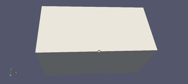
The next figure shows the simulated geometry. In order to save computa- tional power, the full sphere is cut by two symmetry planes reducing the size of the domain by a factor of four. This will not explude any possible solutions, since [4, 5] reported that for a Re = 300 and a Ma = 1.2 the flow around a sphere is steady and rotational symmetric. The Reynolds number Re is defined as Re = U∞d/ν∞ . U∞ is the inflow velocity, d the diamter of the sphere and ν∞ the dynamic viscosity at the inflow. The Mach number is defined as Ma = U∞/c∞ . c∞ is the speed of sound at the inflow. The flow at the inflow is directed in x-direction. The planes cutting the sphere are defined as symmetry plans. For all other planes a inflow-outflow boundary condition is applied. This means that for the velocity and energy if the flow is pointing inside the computational domain a fixed value boundary condi- tion is applied and if the flow leaves the domain a zero gradient boundary condition is applied. For the pressure it is the way around: If the flow is directed inside the domain a zero gradient condition is used and if the flow is pointing outside the domain a fixed value condition is used. Since the flow at this Re is laminar, no other equations are solved. The extension of the computational domain was 20 diameters upstream and downstream of the sphere. In lateral directions it was also 20 diameters. Two different meshes (a coarse and fine one) are compared with each other. Furthermore two additional AMR simulations are performed: the two simulations differ in the threshold for which the mesh is refined.
Mesh generation
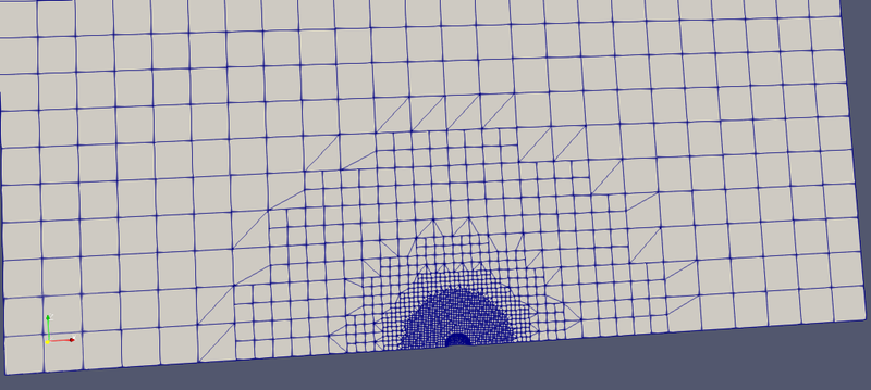
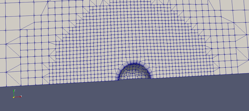
The next figures shows the meshing strategy adopted. The figures show the coarse mesh. The difference between the coarse and fine mesh is the innermost refinement level. For the coarse we use a level of 4 and for the fine one a level of 6. The purpose was to compare the solutions achieved on this two meshes with the solution achieved with the AMR starting with the coarse mesh and allowing a refinement of level 6. Five refinements regions are chosen to gradually increase the resolution from the coarsest level to the finest level around the sphere. The initial grid had hexagonal cells of 1.83 × 10⁻⁵ m side length. Note that it is very important to start with cells which are cubes to get a high wall layer coverage near the surface if wall layers are used. The fourth refinement level has a cell side length of 1.14 × 10⁻⁶ m and the sixth refinement level has a cell side length of 2.86 × 10⁻⁷ m. This strategy results in a mesh of approximately 23 000 cells for the coarse mesh and 130 000 cells for the fine mesh. Five layers are used to increase the wall normal resolution to capture the sharp velocity gradients near the wall. The layer coverage is 100%.
Simulation setup
The following listing shows the fvSolution dictionary. The transonic and the consistent switch is set to true. The transonic switch switches a divergence term in the pressure equation on. It transforms the pressure equation from an elliptical equation in case of a incompressible fluid to a hyperbolic equation in case of a compressible fluid. For details how the pressure equation is derived for compressible flows see the book of [3]. The consistent switch specifies that a SIMPLEC algorithm is used. A de- scription of the algorithm SIMPLEC can be found in [3] or also https://openfoamwiki.net/index.php/SimpleFoam for the incompressible case. The implementation for the compressible case is very similar.
solvers {
   p
   {
       solver          GAMG;
       smoother        GaussSeidel;
       tolerance       1e-6;
       relTol          0.01;
   }
   pFinal
   {
       $p;
       relTol          0;
   }
   "(rho|U|k|omega|e|nuTilda)"
   {
       solver          PBiCGStab;
       preconditioner  DILU;
       tolerance       1e-6;
       relTol          0.1;
   }
   "(rho|U|k|omega|e|nuTilda)Final"
   {
       $U;
       relTol          0;
   }
}
PIMPLE
{
   consistent      yes;
   transonic       yes;
   nCorrectors              2;
   nNonOrthogonalCorrectors 1;
   nOuterCorrectors         1;
   pMinFactor      0.1;
   pMaxFactor      4;
}
relaxationFactors {
   equations
   {
       ".*"     1;
   }
}
Regarding the fvSchemes dictionary has to be said that it is important to use a linear scheme for all convective terms to accurately capture the shock. A detailed discussion can be found in https://wiki.openfoam.com/NACA0012_numerical_schemes_variation_by_Michael_Alletto Since we want to compute the steady solution we use a localEuler scheme for the time derivative. The following listing shows the thermophysicalProperties which defines the thermodynamic package used. Note that a small description of the en- tries of the thermophysicalProperties dictionary can be found in https://www.openfoam.com/documentation/user-guide/thermophysical.php or https://cfd.direct/openfoam/user-guide/v6-thermophysical/. What is important for the tutorial is that we used a pure mixture, the specific heat capacity cp (not to be confused with the pressure coefficient) is constant, a ideal or perfect gas is used as equation of state and that the internal energy is solved in the energy transport equation. Regarding the transport properties (i.e. the kinematic viscosity μ) a Sutherland relation is used to describe its change with the temperature. The DNS of [4] also used a Sutherland relation to the describe the temperature dependence of the dynamic viscosity. In the bow shock we have large temperature gradients and a temperature dependent viscosity seams to be more appropriate than a constant one. The constants of the Sutherland model are taken for dry air. For a discussion on the topic see https://curiosityfluids.com/2019/02/15/sutherlands-law/.
thermoType {
   type            hePsiThermo;
   mixture         pureMixture;
   transport       sutherland;
   thermo          hConst;
   equationOfState perfectGas;
   specie          specie;
   energy          sensibleInternalEnergy;
}
mixture {
   specie
   {
       molWeight   28.9;
   }
   thermodynamics
   {
       Cp          1007;
       Hf          0;
   }
   transport
   {
       As          1.4792e-06;
       Ts          116;
   }
}
References
[1] Jeremy Hanke and Martin Krcmar. Adaptive mesh refinement of hypersonic shock and wake structures in simcenter star-ccm+. In AIAA AVIATION 2020 FORUM, page 3227, 2020.
[2] Saumitra Vinay Joshi. Adaptive mesh refinement in openfoam with quantified error bounds and support for arbitrary cell-types. 2016.
[3] Fadl Moukalled, L Mangani, Marwan Darwish, et al. The finite volume method in computational fluid dynamics, volume 113. Springer, 2016.
[4] T Nagata, T Nonomura, S Takahashi, and K Fukuda. Direct numerical simulation of subsonic, transonic and supersonic flow over an isolated sphere up to a reynolds number of 1000. Journal of Fluid Mechanics, 904, 2020.
[5] Takayuki Nagata, Taku Nonomura, Shun Takahashi, Yusuke Mizuno, and Kota Fukuda. Investigation on subsonic to supersonic flow around a sphere at low reynolds number of between 50 and 300 by direct numerical simulation. Physics of Fluids, 28(5):056101, 2016.
[6] J Sinclair and Xinjun Cui. A theoretical approximation of the shock standoff distance for supersonic flows around a circular cylinder. Physics of Fluids, 29(2):026102, 2017.


